Geometry Model
Contents
Geometry Model
Detector types
Computing all individual measurement footprint is complex, time consuming, and unnecessary for low geometrical search
results accuracy. We use an approach to derive observation footprints by using a simplified sensor geometry model for
four detector types: IN-SITU, POINT, LINE, FRAME.
Detector types and related parameters are defined in addendum IK files.
IN-SITU detector
No SPICE detector boresight defined.
Used to model in-situ instruments.
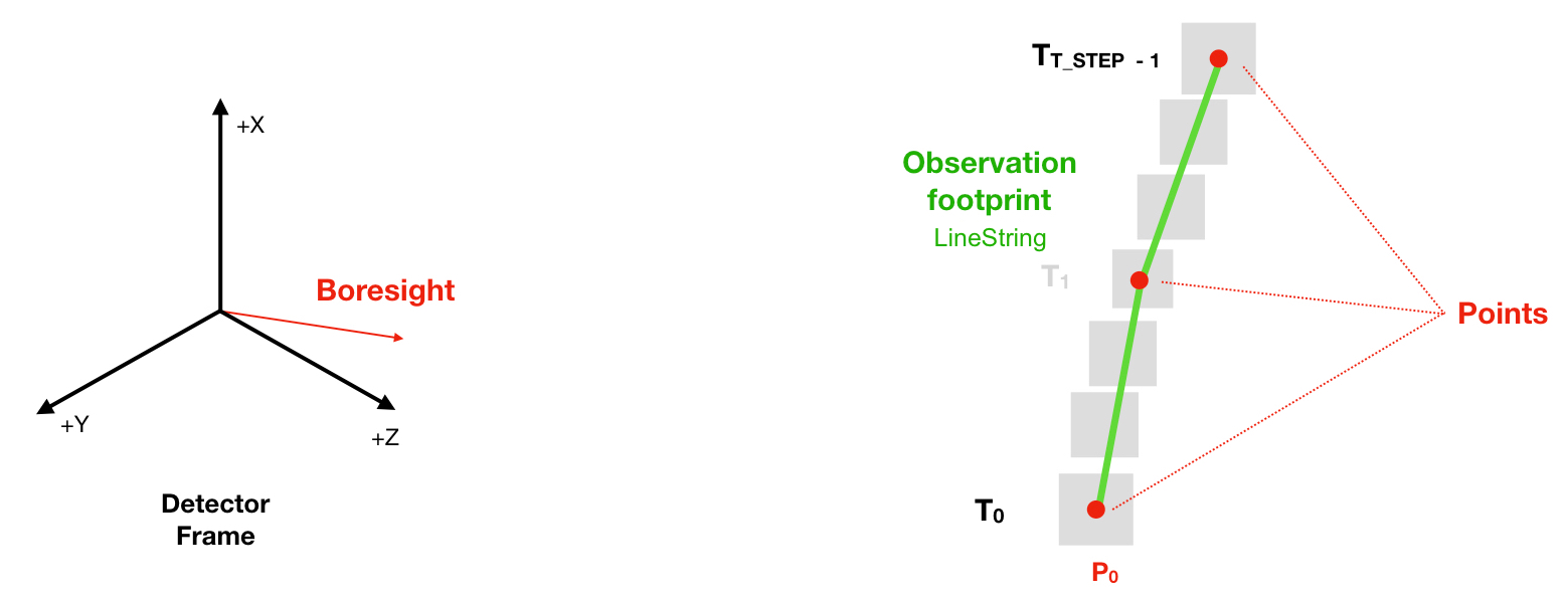
POINT detector
Solely defined by a SPICE detector boresight.
Used to model spectrometers.
Spatial resolution (horizontal or vertical) is given by the number of computation time steps (
T_STEPS).Footprint GeoJSON Geometry type is a
LineStringorMultiLineString(for split footprint).

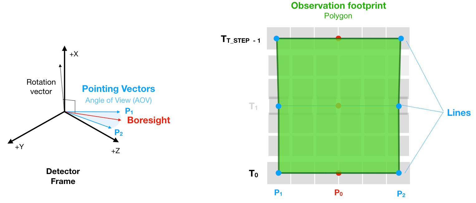
LINE detector
Defined by a SPICE detector boresight, an angle-of-view (AOV) and rotation vector
Used to model whiskbroom and push-broom cameras.
Spatial resolution is given by the AOV, which can be mode dependent, and the number of computation time steps (
T_STEPS).Footprint GeoJSON Geometry type is a
PolygonorMultiPolygon(for split footprint).

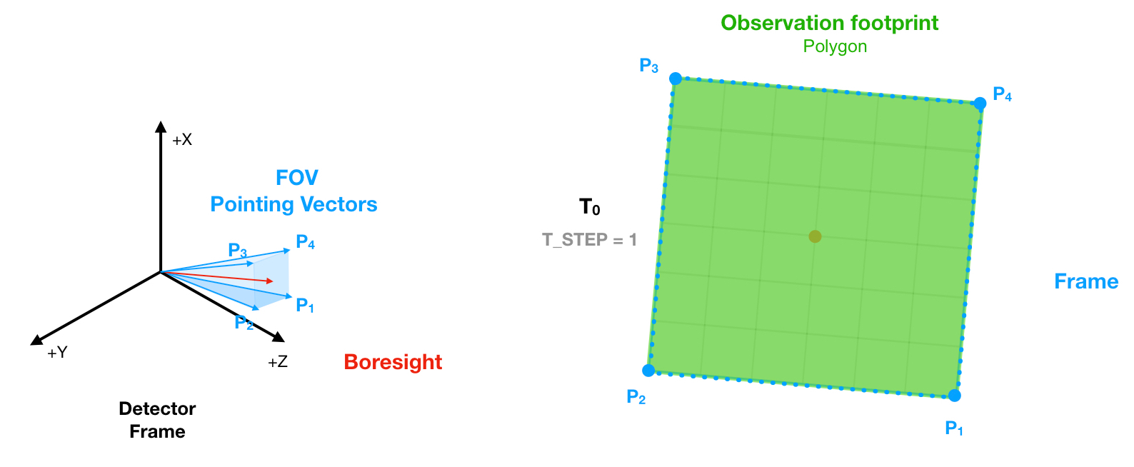
FRAME detector
Defined by a SPICE detector boresight and a fielf-of-view (FOV)
Used to model “instant-acquisition” framing cameras (eg: MEX/HRSC SRC, TGO/CASSIS).
Single-measurement observation only.
FOV pointing vectors are interpolated along each bound vector.
A sub-framing behaviour can be defined for a FRAME detector. The sub-frame FOV is computed based on two parameters:
detector_fov_ref_ratioanddetector_fov_cross_ratioby thegeogen.coverage.Detector.get_geometry()method, scaling down the detector full FOV in the “reference” and “cross” directions (eg: +X and +Y axis of the detector frame).Footprint GeoJSON Geometry type is a
PolygonorMultiPolygon(for split footprint).

Observation Footprint
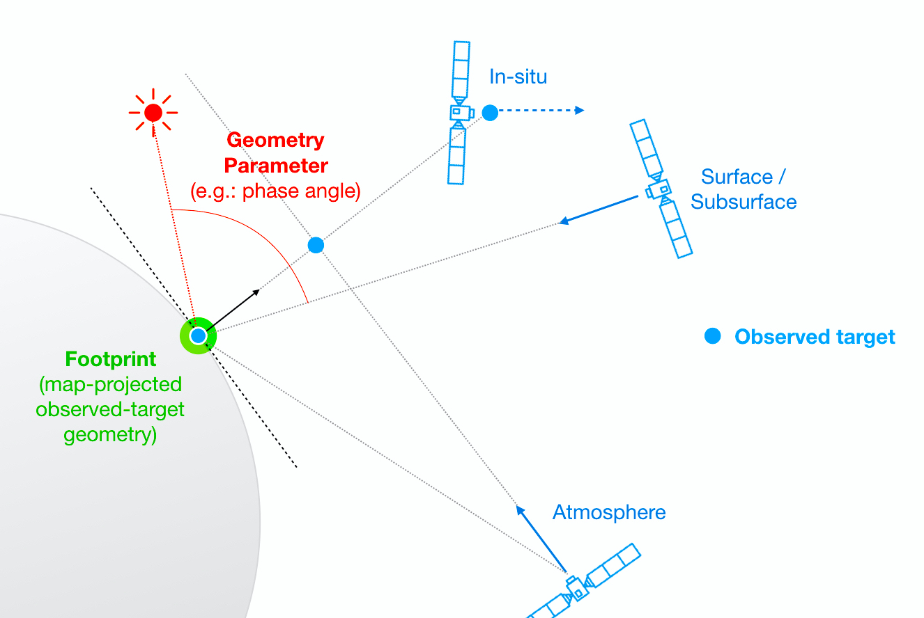
A footprint is defined as the “observed-target” geometry projected onto the surface of the target body, made of a a set surface points:
for surface observations, a surface point is the intersection between the detector boresight and the target body surface,
for off-surface (atmosphere/exosphere) observations, a surface point is the nearest on the target body surface and the detector boresight,
for in-situ observations, there is no footprint.

Geometry Parameters
Geometry parameters includes timing information, parameters that are independent of the spacecraft position, parameters that are dependent of the spacecraft position but independent of the spacecraft pointing, and parameters that are dependent of the spacecraft pointing.
Coordinate system and units:
Longitudes and latitudes are expressed in planetocentric coordinate system, in degrees.
All angles are expressed in degrees.
All distance are expressed in kilometers.
Timing
Earliest UTC time corresponding to the observation footprint. |
|
Latest UTC time corresponding to the observation footprint. |
|
Reference UTC time at which most geometry parameters are computed (min_*/max_* parameters are computed taking into account for all observation geometry computation times. The reference time is defined as the time between the start and stop time). |
Spacecraft position independent
The following parameters relates to the Sun as seen from the target, independently of the spacecraft position:
Planetocentric longitude (Ls) of the sun for the target body at the reference time. The planetocentric longitude is the angle between the body-sun vector at the time of interest and the body-sun vector at the vernal equinox. |
|
Latitude of the sub-solar point on the target body at the reference time. The sub-solar point is the point on a body’s reference surface where a line from the body center to the sun center intersects that surface. |
|
Longitude of the sub-solar point on the target body at the reference time. The sub-solar point is the point on a body’s reference surface where a line from the body center to the sun center intersects that surface. |
|
Distance from the center of the sun to the center of the target body at the reference time. |
Spacecraft pointing independent
The following parameters relates to Sun and the target as seen from the spacecraft position, but are independent of the spacecraft pointing:
Distance from the spacecraft to the center of the sun at the reference time. |
|
Distance from the spacecraft to the sub-spacecraft point on the target body at the reference time. |
|
Distance from the spacecraft to the center of the target body at the treference time. |
|
Latitude of the sub-spacecraft point on the target body at the reference time. |
|
Longitude of the sub-spacecraft point on the target body at the reference time. |
|
Solar zenith angle at the sub-spacecraft point on the target body surface at the reference time. The solar zenith angle is the angle subtended between the direction towards the Sun and the local normal at the surface. |
|
Right ascension of the position vector of the target body center as seen from the spacecraft in the Earth mean equator and equinox frame (J2000). |
|
Declination of the position vector of the target body center as seen from the spacecraft in the Earth mean equator and equinox frame (J2000). |
|
Right ascension of the position vector of the Sun as seen from the spacecraft in the Earth mean equator and equinox frame (J2000). |
|
Declination of the position vector of the Sun as seen from the spacecraft in the Earth mean equator and equinox frame (J2000). |
|
X component of the position vector from spacecraft to Sun, expressed in J2000 coordinates, and corrected for light time and stellar aberration, evaluated at the reference time. |
|
Y component of the position vector from spacecraft to Sun, expressed in J2000 coordinates, and corrected for light time and stellar aberration, evaluated at the reference time. |
|
Z component of the position vector from spacecraft to Sun, expressed in J2000 coordinates, and corrected for light time and stellar aberration, evaluated at the reference time. |
|
X component of the velocity vector of Sun relative to the spacecraft, expressed in J2000 coordinates, and corrected for light time and stellar aberration, evaluated at the reference time. |
|
Y component of the velocity vector of Sun relative to the spacecraft, expressed in J2000 coordinates, and corrected for light time and stellar aberration, evaluated at the reference time. |
|
Z component of the velocity vector of Sun relative to the spacecraft, expressed in J2000 coordinates, and corrected for light time and stellar aberration, evaluated at the reference time. |
|
X component of the position vector from the spacecraft to target body center, expressed in J2000 coordinates, and corrected for light time and stellar aberration, evaluated at the reference time. |
|
Y component of the position vector from the spacecraft to target body center, expressed in J2000 coordinates, and corrected for light time and stellar aberration, evaluated at the reference time. |
|
Z component of the position vector from the spacecraft to target body center, expressed in J2000 coordinates, and corrected for light time and stellar aberration, evaluated at the reference time. |
|
X component of the velocity vector of the target body center relative to the spacecraft, expressed in J2000 coordinates, and corrected for light time and stellar aberration, evaluated at the reference time. |
|
Y component of the velocity vector of the target body center relative to the spacecraft, expressed in J2000 coordinates, and corrected for light time and stellar aberration, evaluated at the reference time. |
|
Z component of the velocity vector of the target body center relative to the spacecraft, expressed in J2000 coordinates, and corrected for light time and stellar aberration, evaluated at the reference time. |
Spacecraft pointing independent
Spacecraft pointing independent parameters values are always set to null for IN-SITU instruments.
The following parameters relates to the detector boresight:
Right ascension of the detector boresight vector, in the Earth mean equator and equinox frame (J2000), at the reference time. |
|
Declination of the detector boresight vector, in the Earth mean equator and equinox frame (J2000), at the reference time. |
|
The separation angle between the detector line-of-sight (boresight) and the target body center as seen from the spacecraft, at the reference time. |
|
Separation angle between the detector line-of-sight and the position vector of the Sun as seen from the spacecraft, at the reference time. |
The following parameters relates to the observation footprint, and to viewing and illuminating conditions at the observed target points:
Latitude of the observation footprint center point. |
|
Longitude of the observation footprint center point. |
|
Whether or not observation footprint is crossing the target body antimeridian. |
|
Whether or not observation footprint is crossing the target body North Pole. |
|
Whether or not observation footprint is crossing the target body South Pole. |
|
Westernmost observation longitude of the footprint. |
|
Easternmost observation longitude of the footprint. |
|
Minimum observation latitude of the footprint. |
|
Maximum observation latitude of the footprint. |
|
Local solar time for the surface point, evaluated at the reference time. The local solar time is the angle between the planetocentric longitude of the Sun, as viewed from the center of the target body, and the planetocentric longitude of the surface point, expressed on a “24 hour” clock. |
|
Minimum incidence angle. The incidence angle is the angle between the local vertical at a given surface point and the vector from the surface point to the sun. |
|
Maximum incidence angle. The incidence angle is the angle between the local vertical at a given surface point and the vector from that the surface point to the sun. |
|
Minimum emission angle. The emission angle is the angle between the surface normal at a given surface point and the vector from the surface point to the spacecraft. |
|
Maximum emission angle. The emission angle is the angle between the surface normal at a given surface point and the vector from the surface point to the spacecraft. |
|
Minimum phase angle. The phase angle is the angle between the vectors from the surface point to the spacecraft and from the surface point to the Sun. |
|
Maximum phase angle. The phase angle is the angle between the vectors from the surface point to the spacecraft and from the surface point to the Sun. |
|
Minimum slant distance. The slant distance is the distance from the spacecraft to the nearest point on the detector line-of-sight to the target body surface. |
|
Maximum slant distance. The slant distance is the distance from the spacecraft to the nearest point on the detector line-of-sight to the target body surface. |
|
Minimum tangent altitude. The tangent altitude is the distance from the target body surface nearest point to the detector line-of-sight. |
|
Maximum tangent altitude. The tangent altitude is the distance from the target body surface nearest point to the detector line-of-sight. |
|
Minimum across-track instantaneous field-of-view (iFOV) target point spatial resolution. |
|
Maximum across-track instantaneous field-of-view (iFOV) target point spatial resolution. |
